-
Working pressure: 7~13bar 100~190psig Air delivery: 2.5~102m3/min 88~3600cfm Working power: 22~560kw 30~750hp
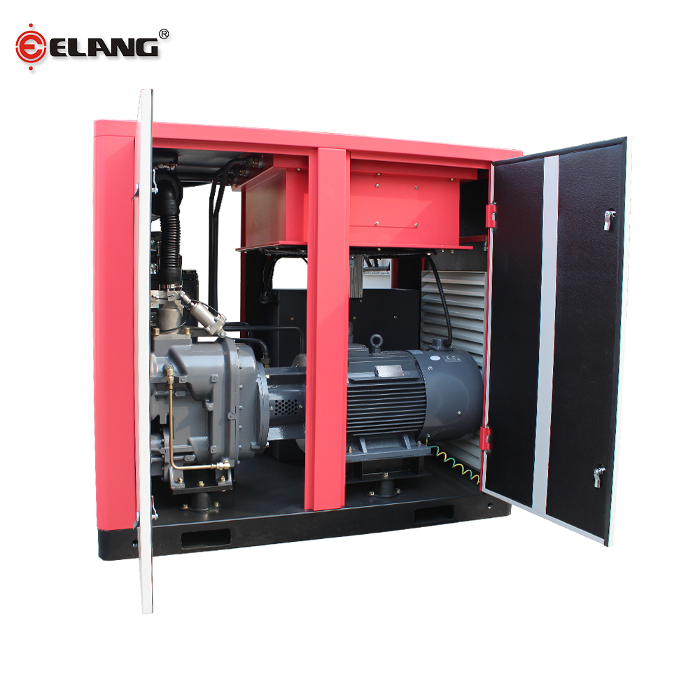
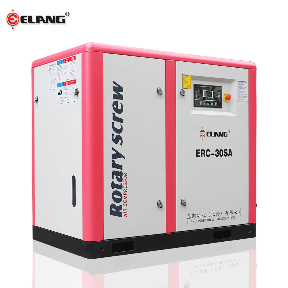 direct driven
 -
Working pressure: 7~13bar 100~190psig Air delivery: 0.7~3.8m3/min 25~134cfm Working power: 7.5~22kw 10~30hp
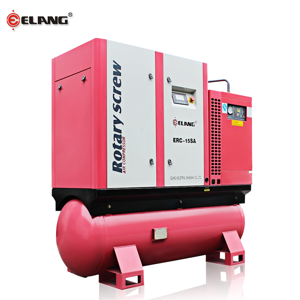 combined
 -
Working pressure: 6.5~13bar 95~190psig Air delivery: 0.5~102.0m3/min 17.7~3600cfm Working power: 5.5~560kw 7.5~750hp Frequency range: 40%~100%
 VSD
VSD -
Working pressure: 6.5~13bar 95~190psig Air delivery: 0.5~102.0m3/min 17.7~3600cfm Working power: 5.5~560kw 7.5~750hp Frequency range: 40%~100%
 PM
PM -
Working pressure: 4.0~13bar 58~189psig Air delivery: 9.5~61.9m3/min 335.5~2189cfm Working power: 55~315kw 75~420hp
 two-stage
 -
Working pressure: 7~35bar 100~508psig Air delivery: 5.0~37.0m3/min 177~1310cfm Working power: 37~447kw 50~600hp
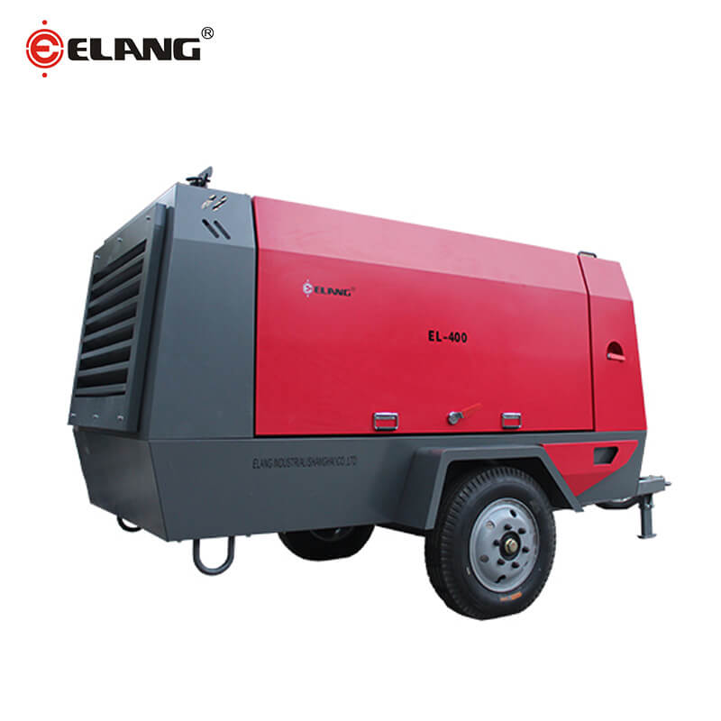 portable

System Description of Screw Air Compressor Ⅱ
...
System Description of Screw Air Compressor Ⅱ
Oct 14, 2020
As you know we have made the detailed function description of every component of screw compressor in the previous article, today we will start to describe about the oil system and the cooling system of screw air compressor.
The workflow of lubricating oil
Due to the gas pressure in the oil-gas tank, the lubricating oil is pressed into the oil cooler. After the lubricating oil is cooled in the cooler, it passes through the oil filter to remove impurities and particles, and then divides itself into two paths. One is sprayed into the compression chamber from the lower end of the machine body to cool the compressed air, and the other way is connected to both ends of the machine body to lubricate the bearing set and transmission gear, and then (the lubricating oil in each part) is collected in the compression chamber and discharged with the compressed air. The compressed air mixed with oil enters the oil-gas tank to separate a large part of the oil. The remaining oil-containing mist air passes through the oil separator to filter out the remaining oil, and then enters the after cooler through the pressure maintenance valve for cooling, and then it can be sent to the use-system.
Function description of each component of the oil system:
1.Oil cooler
The cooling method of the oil cooler is the same as that of the air after cooler, and there are two cooling methods of air cooling and water cooling. If the environmental conditions are not good, the fins of the air-cooled cooler are easily covered by dust, which affects the cooling effect, and the exhaust temperature will be too high and cause the machine to trip. Therefore, every considerable period of time, compressed air is used to blow off the dust on the surface of the fin. If it cannot be blown clean, it must be cleaned with a solvent. Be sure to keep the cooling surface of the cooler clean. When the shell-and-tube cooler is blocked, it must be soaked in a special syrup, and the scale clogged in the tube must be removed mechanically. Make sure to clean it completely.
2. Oil filter
The oil filter is a paper filter whose function is to remove impurities in the oil such as metal particles, oil degradation, etc. The filtering accuracy is between 5u-10u, and it has a perfect protective effect on the bearing and rotor. The replacement of the oil filter can be judged by its pressure difference indicator and operating time. If the pressure difference indicator light is on, it means that the oil filter is blocked and must be replaced. The oil and oil filter need to be replaced after the first 600 hours of operation of the new machine, and then replaced according to the pressure difference indicator light or operating time. If the oil filter has a large pressure difference and is not replaced, it may cause insufficient oil intake, and the high temperature of the exhaust will trip and the lack of oil will affect the bearing life.
3. Oil separator
The filter element of the oil fine separator is made of multiple layers of fine glass fibers, and the misty oil and gas contained in the compressed air can be almost completely filtered out after passing through the oil fine separator. Under normal operation, the oil fine separator can be used for about 3000-4000 hours. Only the degree of pollution of the lubricating oil and the surrounding environment has a great impact on its life. If the environmental pollution is very serious, you can consider installing a prefilter; the choice of lubricating oil, most do not use fake oil or mixed oil. The outlet of the oil fine separator is equipped with a safety valve and a pressure maintaining valve, and the compressed air is drawn from it and passed to the after cooler. The oil filtered by the fine separator is concentrated in the small circular groove in the center, and then flows back from a return pipe to the throttle check valve and then enters the air intake side of the main engine for circulation, which can prevent the filtered lubricating oil from being used again. The air is discharged.
4. Temperature control valve
A temperature control valve is installed in front of the cooler, its function is to maintain the exhaust temperature above the pressure dew point temperature. When the machine is turned on, the temperature of the lubricating oil is low. At this time, the temperature control valve will automatically open the return circuit, and the oil will directly enter the main engine without passing through the oil cooler. If the oil temperature rises above 60-71℃, the valve will slowly open, and when it reaches 75-85℃, it will fully open. At this time, all the oil will pass through the oil cooler and then enter the body.
Cooling System
1. Air-cooled model
The cold air is drawn in by an axial fan, blown through the cooling fins of the cooler, and exchanges heat with compressed air and lubricating oil to achieve the cooling effect. The maximum allowable ambient temperature of this cooling system is 45℃. If the temperature exceeds 45℃, the system may cause tripping, such as placing it near a high-temperature boiler.
2. Water-cooled model
The design basis of the cooling water temperature is 32℃, so special attention must be paid to the design of the cooling water circulation system. Especially the cooling water quality must meet the general industrial water standard or above, and try to avoid using groundwater. If the water quality is poor, the cooling water tower must regularly add cleaning agents to clean the deposits, so as not to affect the efficiency and life of the cooler. In winter, when the normal temperature is below freezing point, the cooling water in the cooler must be drained after the unit is shut down. Otherwise, the cooler will freeze and crack.
Wish you all could enjoy our content. Next article will be about remaining two systems of screw compressors. Stay tuned!
About Elang:
Product Recommendation:


Company News:
-
Wating to meet you in HANNOVER
Date: Apr 4, 2019
-
Why choose us
Date: Apr 19, 2019
-
Global Recruitment Agency
Date: Jul 19, 2019
-
PTC Asia Invitation
Date: Jul 25, 2019
-
How to Choose the Location of the Air Compressor Room?
Date: Aug 19, 2019
-
How to Arrange an Air Compressor Room?
Date: Sep 4, 2019
-
What are The Precautions for The Connecting Pipe of The Air Compressor?
Date: Sep 16, 2019
-
What are The Requirements for Water-Cooling Air Compressors?
Date: Oct 15, 2019
-
How to Ventilate the Air Compressor Room?
Date: Oct 29, 2019
-
What are The precautions for Installing The Main Circuit Cable of The Air Compressor?
Date: Nov 27, 2019
-
Analysis of Gumming and Carbon Deposit in Screw Air Compressor
Date: Dec 9, 2019
-
Advantages of Elang Oil Free Screw Air Compressor
Date: Dec 16, 2019
-
14 Tips for Compressor Operation
Date: Feb 14, 2020
-
ELANG 200kw Two-stage PM VSD Compressor Loading Flat Rack Container
Date: Mar 3, 2020
-
Why does Two-stage Screw Air Compressor Energy Saving?
Date: May 19, 2020
-
Elang Oil-free Air Compressor for Korean Instant Noodle Factory
Date: May 27, 2020
-
30m3/min 25bar Diesel Portable Compressor Delivery
Date: Jun 1, 2020